Thanks to everyone that came to my talk.
Embedded TDD
This post is still work in progress. It is the basis of a conference presentation I am planning for NDC2015.
Abstract
With the ever increasing complexity of software the need to use development practices like TDD is becoming more and more important. Embedded software development presents an extra set of challenges when practicing TDD. Hardware is often still in development, expensive or has limited availability. Deploying to the target device takes a long time. The target device has limited program space and RAM. For these reasons testing of embedded software is often performed manually (if at all).
There are a large number of papers and articles that focus on TDD for systems without the added complexities of working in an embedded environment. We’ve been developing embedded software using TDD (and a variety of other Agile techniques) for the past 6 years. This paper presents some of the patterns and practices that help us deal with some of the extra complications incurred when practicing TDD in an embedded environment. It covers how we keep the feedback from our tests fast while still running tests on the target hardware. How we mock out dependencies and discusses the advantages and disadvantages to the techniques shown.
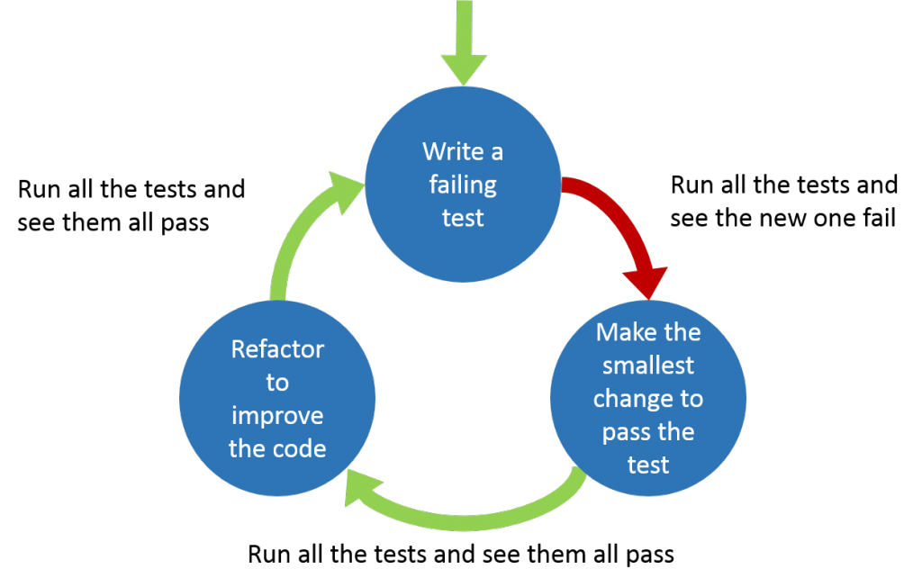
The TDD Cycle
The standard TDD cycle is shown below
TDD tests should be developed FIRST.
- Fast – The tests should be fast to execute. Both fast to execute individual tests and fast for the overall test run.
- Independent/Isolated – The tests should not fail because of external factors. The test does not depend on other tests, they can run in any order.
- Repeatable – Tests must return the same result every time they run, they should not have intermittent results.
- Self-validating – There should be no need for human intervention to determine if a test passes or fails.
- Timely – The tests should be written before the code.
Testing Strategy
Testing on the Target Device
Running tests on the target device is the obvious choice but it’s not without its problems.
Advantages
- Accurate test results (compared to possible issues with running the tests on the host).
Disadvantages
- Slower feedback
- Programming the target device can be slow
- The target device is often not fast when compared to modern PCs so the tests will run more slowly
- Transferring the test results back to the development platform can be slow depending on the method used
- This will slow down your development process
- Make you run test less often, leading to bigger changes and more mistakes and missed execution paths
- Limited code space and RAM
- The tests and the test framework are going to be at least the size of your code if not larger.
- More on ways to overcome this later
- You need target hardware to run the tests
- Limited hardware – not enough for every development pair
- Often expensive
- Sometimes broken
Testing on the Development Platform
Running tests on the development platform solves most (if not all) of the problems encountered with testing on the target platform but introduces some new problems.
Advantages
- Fast feedback
- No code space and/or RAM issues
- No need for target hardware
Disadvantages
- The development platform and target platform are most likely different. There will be differences between the target system and development system (e.g. sizeof(int)). These differences mean some issues will only happen on the target device and you will not detect these on the host.
- Able to write code that may not compile when using the compiler for the target
Dual Targeting
Takes the advantages of both ‘Testing on the Development Platform’ and ‘Testing on the Target Device’ and minimises the disadvantages.
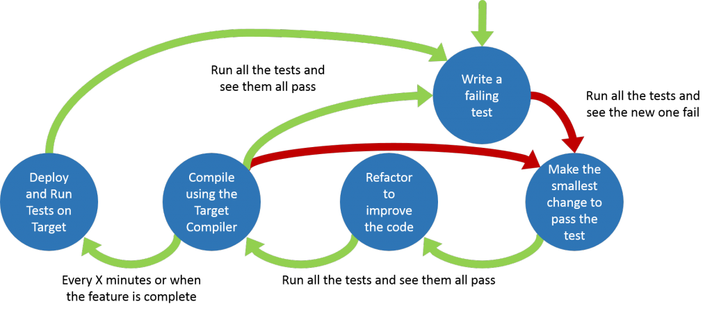
Dual targeting extends the standard TDD cycle
- Red Green Refactor
- After every passing test compile for target to make sure you can! (This checks you haven’t used any unsupported features of the embedded compiler.) Fix any issues encountered.
- Every 15 minutes (or when you’ve finished a logical set of tests) run the tests on the target device and fix any issues encountered.
- More on how to do this with limited hardware availability later
Advantages
- Fast feedback
- More portable code
- Compiling on two different compilers increases the chances of catching issues. (Different compilers given different warnings)
Disadvantages
- Maintaining two builds
- This can be minimised if you can use the same build system and just switch the compiler and linker
Splitting the problem
How you split you code up is going to determine how easy or difficult it is to test.
- Use a modular approach
- Stick to SOLID principles
- Low Coupling
- Thin outer (low level) layer that isn’t tested
Using these principles will help develop a design which is both low coupled and easily testable.
Don’t add extra methods/function just to facilitate testing, the tests should help develop the interface to the code.
Architectural Layers
Application code (Hardware independent) [Easier to test]
Hardware Aware Code
PCB Drivers + HAL/BSP
Processor Drivers + HAL [Harder to test]
The further down the layers (closer to the hardware) you test the harder testing gets.
Mocking
Techniques
- Run time substitution
- Interface (C++)
- Inheritance (C++)
- VTable (C)
- Link time
- Linking other object files (C/C++)
- Weak leaking functions (C)
- Compile time
- Macros (C/C++)
- Templates (C++)
Advantages
- Testing drivers
- Testing error cases from hardware
- Developing before the hardware is ready
Choosing a test framework – consider
- Size of framework
- Portability
- Ease of use
- Options
- Unity
- Embedded Unit
- Google Test
Other
- Integration tests to check integration between classes that had one of them mocked
- Integration tests that check hardware interaction
- Only run on Target
- Using Build/CI servers to run unit tests on hardware
- Polymorphic tests
- Consider what a unit is
Driving a Adafruit 32×32 LED Panel
I recently bought some 32×32 Adafruit LED Panels and found there was a lack of detailed information about how to driver the Panels. Although I found some information I’ve had to reverse engineer certain details and this post details what I’ve discovered.
I’ve included links (at the end of the post) to other on-line resources that I found useful while I was developing my driver code.
Wiring the Panel
The panel has a 16 pin input connector, you will need to connect all of the pins to drive the panel.
The input connector pins
All the pins are 5 Volt inputs. Throughout this post setting a pin high means it should be taken to 5 Volts, setting a pin low means it should be taken to 0 Volts.
| Pin | Purpose |
|---|---|
| CLK | Serial clock, used for clocking out data to indicates which LEDs should be illuminated |
| R1, G1, B1 | Serial data lines for the top half of the Panel |
| R2, G2, B2 | Serial data lines for the bottom half of the Panel |
| LAT | Latch, latches the previously output serial data to the LED drivers |
| /OE | Output enable, sets if the LEDs are illuminated or not |
| A, B, C, D | Sets the address of row of currently illuminated LEDs |
| All other pins | Ground |
Connecting multiple panels
Each panel has a 16 pin output connector, this allows you to daisy chain panels together by connecting the output connector of one panel to the input connector of another panel.
Driving the Panel
The panel is split into two sections, the top 16 rows and bottom 16 rows. The panel only illuminates two rows at any time one from the top section and one from the bottom section. The entire process described below for outputting a single frame needs to be repeated at least 60 times per second, preferably 100-200 times per second to avoid flicker.
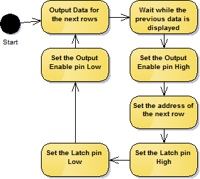
An overview of the basic steps needed to drive the panel is shown below.
Output Data for the next rows
Data is output for two rows at the same time, data for the top sections row is output to the R1, G1, B1 pins and data for the bottom sections row is output to the R2, G2, B2 pins. The data is clocked into shift registers on the panel using the CLK pin.
The data is actually clocked into 6 different shift registers that all have their clock lines linked. The following pseudo C code shows how this is done.
unsigned char Red(unsigned char pixel)   { return ((pixel >> 2) & 0x01); }
unsigned char Green(unsigned char pixel) { return ((pixel >> 1) & 0x01); }
unsigned char Blue(unsigned char pixel)  { return ((pixel >> 0) & 0x01); }

void OutputRowData(unsigned char *topData, unsigned char *bottomData)
{
    for(int column = 0; column < 32; ++column)
    {
        // Set the state of the LEDs for the pixel in
        // the top half of the panel
        R1_STATE = Red(topData[column]);
        G1_STATE = Green(topData[column]);
        B1_STATE = Blue(topData[column]);

        // Set the state of the LEDs for the pixel in
        // the bottom half of the panel
        R2_STATE = Red(bottomData[column]);
        G2_STATE = Green(bottomData[column]);
        B2_STATE = Blue(bottomData[column]);

        // Clock the pixels into the shift registers
        CLK_STATE = 1;
        Pause(); // Depending on the speed of you processor,
                 // this might not be needed
        CLK_STATE = 0;
    }
}
Wait while the previous data is displayed
Wait for an amount of time, this time plus the time to output the data for the next row determines the on time for the LEDs on an individual row. The overall brightness of the display can be controlled by varying ratio of the LEDs on time and their off time.
Set the Output Enable pin High
This switches the LED outputs off (the Output Enable pin is active low). It’s best to turn the LED outputs off when changing rows to stop any undesired artifacts.
Set the address of the next row
Setting the address requires setting the A, B, C and D pins. These work as a 4-bit row address so if they are all 0 the 1st and 16th rows will be illuminated.
The address determines which two rows of LEDs will be illuminated.
Set the Latch pin High, Set the Latch pin Low
Toggling the LAT pin high then low will transfer the data clocked into the shift registers to the output pins of the shift register.
Set the Output Enable pin Low
This switches the LED outputs back on.
Looping
Once rows 16 and 32 have been output start again at rows 1 and 17.
Improvements
This process will only give you 3-bit pixel data so the possible colours are limited to Black, Red, Green, Blue, Cyan, Magenta, Yellow and White. It is possible to get the display to display more colours but I’ll save that for another blog post.
Links
https://learn.adafruit.com/32×16-32×32-rgb-led-matrix/
http://bikerglen.com/projects/lighting/led-panel-1up/


