
Slides from my talk at the Software Cornwall Business Connect 2017 Event on ‘TDD Driving Quality’.
Category Archives: Development
DHT11 & PCF8591 Arduino Libraries
As part of the Eden of Things project I’ve been working on recently I developed some drivers for the DHT11 humidity & temperature sensor and the PCF8591 ADC & DAC chips. You can download the libraries zip archives from my projects page.
I’m aiming to get these distributed using the Arduino library manager when I get a chance.
Eden of Things
I’ve been helping out with an work experience week at the Eden Project developing a sensor network to monitor the Biomes. We used ESP8266 to read sensors, logged the readings to a central server and then displaying that data on displays that allow visitors to see how the conditions in the Biomes change throughout the day.
The event went well and by the end we had a basic walking skeleton to demonstrate to the guests on the final day. The demo consisted of the ESP8266 micro controllers reading data from the sensors, sending it to the core server and the UI TVs pulling the data from the server and displaying it.
I was the mentor for the sensors team, our week consisted of:
Day 1
- The day started with Scrum tennis as a team building exercise.
- TDD training in cyber-dojo.
- An introduction to the project.
- Wiring up the ESP8266 modules on bread boards so we could program them.
- At the end of the day we found that the development tools did not work on the Raspberry Pis we were planning to use, after a quick search on the internet it was decided we would use x86 Linux boxes.
Day 2
- Getting the sensors working
- Setting up a Web Server on the ESP8266
Day 3
- WiFi range testing
- Building PCBs
- Initial development of the code to send the sensor data using a HTTP POST
Day 4 – I wasn’t there so Mike helped the team
Day 5
- More PCB building
- Development of code the calibrate the sensors. We sadly didn’t have time for the code to make it into the final demo

At the end of Day 2 of the Eden of Things it’s customer demo time.
Driving a Adafruit 32×32 LED Panel
I recently bought some 32×32 Adafruit LED Panels and found there was a lack of detailed information about how to driver the Panels. Although I found some information I’ve had to reverse engineer certain details and this post details what I’ve discovered.
I’ve included links (at the end of the post) to other on-line resources that I found useful while I was developing my driver code.
Wiring the Panel
The panel has a 16 pin input connector, you will need to connect all of the pins to drive the panel.
The input connector pins
All the pins are 5 Volt inputs. Throughout this post setting a pin high means it should be taken to 5 Volts, setting a pin low means it should be taken to 0 Volts.
| Pin | Purpose |
|---|---|
| CLK | Serial clock, used for clocking out data to indicates which LEDs should be illuminated |
| R1, G1, B1 | Serial data lines for the top half of the Panel |
| R2, G2, B2 | Serial data lines for the bottom half of the Panel |
| LAT | Latch, latches the previously output serial data to the LED drivers |
| /OE | Output enable, sets if the LEDs are illuminated or not |
| A, B, C, D | Sets the address of row of currently illuminated LEDs |
| All other pins | Ground |
Connecting multiple panels
Each panel has a 16 pin output connector, this allows you to daisy chain panels together by connecting the output connector of one panel to the input connector of another panel.
Driving the Panel
The panel is split into two sections, the top 16 rows and bottom 16 rows. The panel only illuminates two rows at any time one from the top section and one from the bottom section. The entire process described below for outputting a single frame needs to be repeated at least 60 times per second, preferably 100-200 times per second to avoid flicker.
An overview of the basic steps needed to drive the panel is shown below.
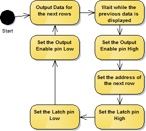
Output Data for the next rows
Data is output for two rows at the same time, data for the top sections row is output to the R1, G1, B1 pins and data for the bottom sections row is output to the R2, G2, B2 pins. The data is clocked into shift registers on the panel using the CLK pin.
The data is actually clocked into 6 different shift registers that all have their clock lines linked. The following pseudo C code shows how this is done.
unsigned char Red(unsigned char pixel)   { return ((pixel >> 2) & 0x01); }
unsigned char Green(unsigned char pixel) { return ((pixel >> 1) & 0x01); }
unsigned char Blue(unsigned char pixel)  { return ((pixel >> 0) & 0x01); }

void OutputRowData(unsigned char *topData, unsigned char *bottomData)
{
    for(int column = 0; column < 32; ++column)
    {
        // Set the state of the LEDs for the pixel in
        // the top half of the panel
        R1_STATE = Red(topData[column]);
        G1_STATE = Green(topData[column]);
        B1_STATE = Blue(topData[column]);

        // Set the state of the LEDs for the pixel in
        // the bottom half of the panel
        R2_STATE = Red(bottomData[column]);
        G2_STATE = Green(bottomData[column]);
        B2_STATE = Blue(bottomData[column]);

        // Clock the pixels into the shift registers
        CLK_STATE = 1;
        Pause(); // Depending on the speed of you processor,
                 // this might not be needed
        CLK_STATE = 0;
    }
}
Wait while the previous data is displayed
Wait for an amount of time, this time plus the time to output the data for the next row determines the on time for the LEDs on an individual row. The overall brightness of the display can be controlled by varying ratio of the LEDs on time and their off time.
Set the Output Enable pin High
This switches the LED outputs off (the Output Enable pin is active low). It’s best to turn the LED outputs off when changing rows to stop any undesired artifacts.
Set the address of the next row
Setting the address requires setting the A, B, C and D pins. These work as a 4-bit row address so if they are all 0 the 1st and 16th rows will be illuminated.
The address determines which two rows of LEDs will be illuminated.
Set the Latch pin High, Set the Latch pin Low
Toggling the LAT pin high then low will transfer the data clocked into the shift registers to the output pins of the shift register.
Set the Output Enable pin Low
This switches the LED outputs back on.
Looping
Once rows 16 and 32 have been output start again at rows 1 and 17.
Improvements
This process will only give you 3-bit pixel data so the possible colours are limited to Black, Red, Green, Blue, Cyan, Magenta, Yellow and White. It is possible to get the display to display more colours but I’ll save that for another blog post.
Links
https://learn.adafruit.com/32×16-32×32-rgb-led-matrix/
http://bikerglen.com/projects/lighting/led-panel-1up/